Acoustic Intelligence for Industrial Motors
Non-contact acoustic monitoring.
For proactive maintenance of industrial motors.
AcouTec records the sound of a running motor with a microphone array and analyses its acoustic signature with signal processing and machine learning, without physically contacting or modifying the machine.
The Problem
Unexpected motor failures are costly
Asynchronous (induction) motors drive pumps, fans, compressors, conveyors and production lines in many industrial facilities. Their maintenance is often either reactive or scheduled.
Repair after failure
Unplanned downtime, damaged equipment and disrupted production.
Fixed schedules
Parts may be replaced earlier than necessary, or a developing fault may go unnoticed until the next inspection.
Limited insight into actual condition
Neither approach gives continuous information about how the machine is actually behaving between inspections.
AcouTec
AcouTec listens to the machine
AcouTec records the sound of a running motor and analyses its acoustic signature to classify its operating condition, without physically contacting or modifying the machine.
Non-contact sensing
Records airborne acoustic emissions; the motor is not modified.
Four-channel acquisition
The Gen 2 hardware records four synchronized microphone channels. The added value of multiple channels over a single microphone is part of the ongoing validation.
Acoustic signal processing + machine learning
Noise profiling, filtering, wavelet and spectral features, and a linear SVM classifier turn the recorded sound into a condition class.
Condition monitoring without physical contact with the motor
A descriptive comparison of sensing approach and access requirements. It does not compare measured performance, and AcouTec has not been benchmarked against these methods.
| Approach | Sensing and access requirement | Typical measurement |
|---|---|---|
| Vibration analysis | Physical sensor (accelerometer) mounted on the machine | Fixed sensors or portable measurements |
| Motor current signature analysis | Electrical access to the motor supply | Measurements from electrical signals |
| Handheld ultrasound inspection | Handheld instrument used by an operator | Spot measurements, operator-dependent |
| AcouTec | Non-contact sensing of airborne sound; the motor is not modified | Multi-channel acoustic acquisition (four channels on Gen 2); validation in progress |
AcouTec is designed as a multi-channel acoustic acquisition and analysis system for asynchronous motors.
Technology
From motor sound to motor condition
AcouTec is an acoustic sensing, signal-processing and machine-learning system. Below: the idea at a glance, the full pipeline, and the techniques behind it.
A running motor continuously emits sound. Illustration.
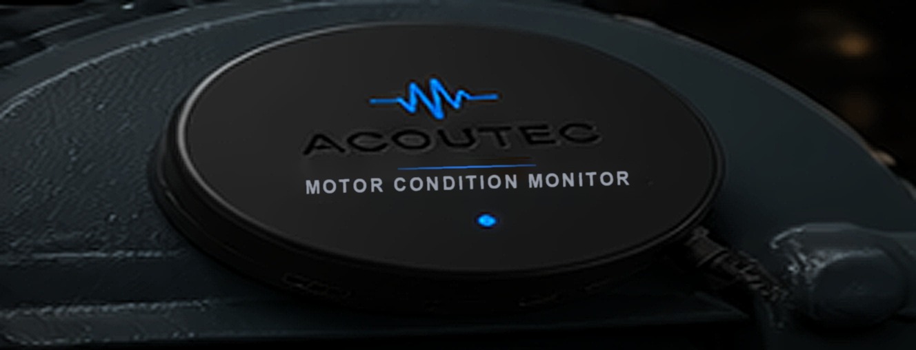
The Gen 2 electronics sit inside a compact enclosure. It records airborne sound and does not modify the motor. Concept render; the final enclosure may differ.
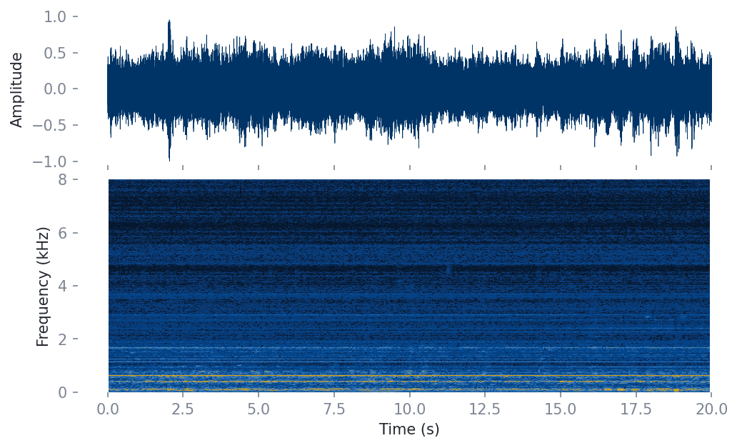
Airborne sound is recorded, filtered and analysed in time and frequency. Example: one Gen 1 recording.
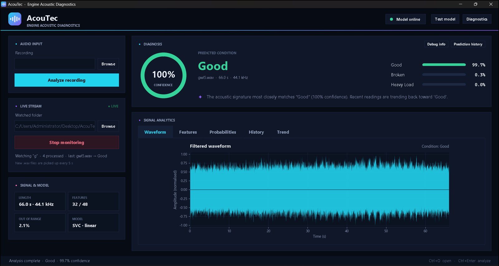
The Logisial desktop software (prototype) shows the predicted class and its probabilities. Example screen, not a validation result. Full screens below.
The classifier outputs one of the three conditions it was trained on in the Gen 1 dataset.
What is not claimed (yet)
- No estimate of fault severity, remaining life or time to failure.
- Only three conditions are validated; other fault types, such as bearing faults, are not yet validated.
- The system records airborne sound; ultrasonic sensing is not part of the validated system.
The Logisial desktop software
A prototype desktop application that analyses a recording and shows the predicted condition, the class probabilities and the signal behind them.
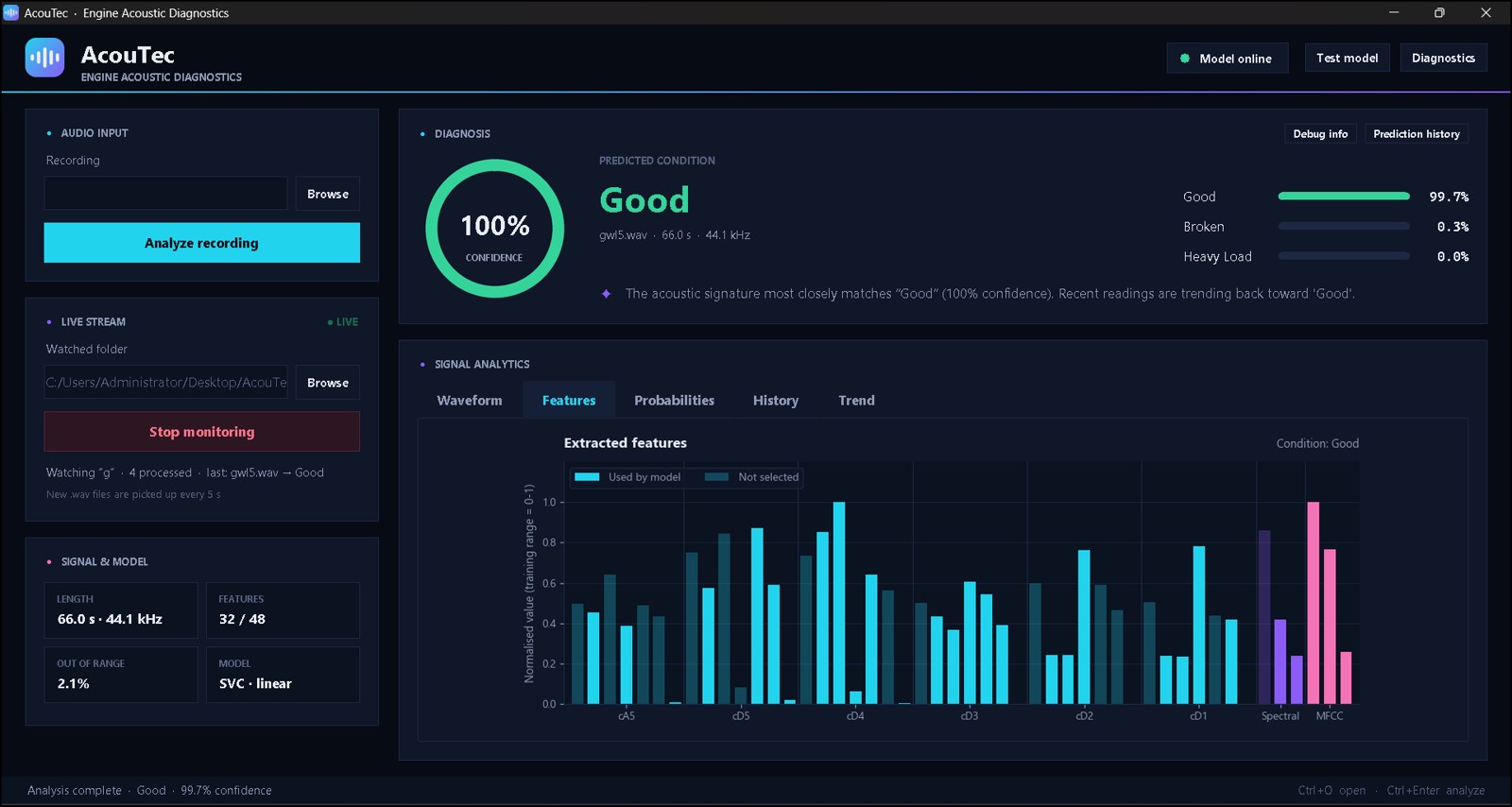
- Analyses a recording and returns a condition class with a probability for each class.
- Tabs for waveform, features, probabilities, history and trend.
- Can watch a folder and analyse new recordings automatically (checked every 5 seconds).
Example screens for a single recording. The confidence value is the model's output for that recording, not a measure of accuracy; see the Evidence section for validation results. Click a screen to enlarge it.
The full pipeline
Sensing
- Industrial motorSource of the acoustic emissions
- Four microphonesSynchronized capture (Gen 2)
- Acquisition hardwareDigital acquisition of the channels
Signal processing
- Signal processingNoise profiling, spectral subtraction, band-pass filtering
- Feature extractionWavelet and spectral features
- Feature selectionKeeps the most informative features
Classification
- Multiclass classificationSupport Vector Machine (SVM)
- LogisialDesktop software that presents the result
- Motor conditionOutput class, e.g. Good, Broken Rotor, Heavy Load
Techniques used
Noise profiling & spectral subtraction
A background-noise spectrum is estimated from a short initial part of each recording and subtracted from the signal's magnitude spectrum.
Butterworth filtering
A 6th-order Butterworth band-pass filter keeps the frequency range of interest.
Wavelet decomposition
Daubechies-4 (db4) wavelet, five levels. Seven statistics per band (mean, standard deviation, maximum, minimum, median, skewness, kurtosis) give 42 features.
Acoustic features
Spectral centroid, spectral rolloff, zero-crossing rate and MFCC 1–3 add six more, for 48 features in total.
Feature selection
SVM-based selection keeps the most informative features: 24 of the 48 in the Gen 1 validation run.
SVM classification
A linear-kernel Support Vector Machine assigns one of three classes: Good, Broken Rotor or Heavy Load.
Hardware generations
- ESP32
- 4× INMP441 microphones
- 3D-printed prototype
- Used for the initial proof of concept and dataset experiments
- The results in the Evidence section come from this generation
- Purpose-built acquisition PCB
- Four-channel synchronized acoustic acquisition
- Current hardware platform
- Real-motor validation underway; no formal results yet
Evidence
What has been demonstrated so far
The results below come from an early controlled experiment with first-generation (Gen 1) hardware. They are not industrial-scale validation, and they do not describe the Gen 2 system.
108
labeled recordings
Gen 1 · single-channel · 44.1 kHz
48 → 24
extracted → selected features
- Noise profiling, band-pass filter
- Wavelet + spectral features
- Linear SVM, 3 classes
64 training · 22 validation · 22 test (split by recording)
21 / 22
test recordings correct
- Validation: 21 / 22 correct
- Training: 64 / 64 correct
Early experimental result, not real-world accuracy
Early controlled dataset
- Small dataset (22 test recordings)
- Controlled recording conditions
- Single recording source / motor setup
Gen 2 on real motors
- Real industrial motor recordings
- Robustness to industrial noise
- Multi-brand generalization
Limitations of this early experiment
- Small dataset
- Controlled recording conditions
- Single recording source / motor setup
- No factory-noise validation yet
- Generalization across motor brands and industrial environments is not yet established
The 21 / 22 results (95.5%) are early experimental figures on a small dataset. They should not be read as guaranteed real-world accuracy.
The Gen 1 data behind the result
Confusion matrices: rows are the actual condition, columns the predicted one. Numbers are counts of recordings.
| Good | Broken | Heavy | |
|---|---|---|---|
| Good | 6 | 0 | 1 |
| Broken | 0 | 8 | 0 |
| Heavy | 0 | 0 | 7 |
One Good recording was classified as Heavy Load.
| Good | Broken | Heavy | |
|---|---|---|---|
| Good | 7 | 0 | 0 |
| Broken | 1 | 6 | 0 |
| Heavy | 0 | 0 | 8 |
One Broken Rotor recording was classified as Good.
| Good | Broken | Heavy | |
|---|---|---|---|
| Good | 22 | 0 | 0 |
| Broken | 0 | 21 | 0 |
| Heavy | 0 | 0 | 21 |
Shows fit to the training data, not performance on new recordings.
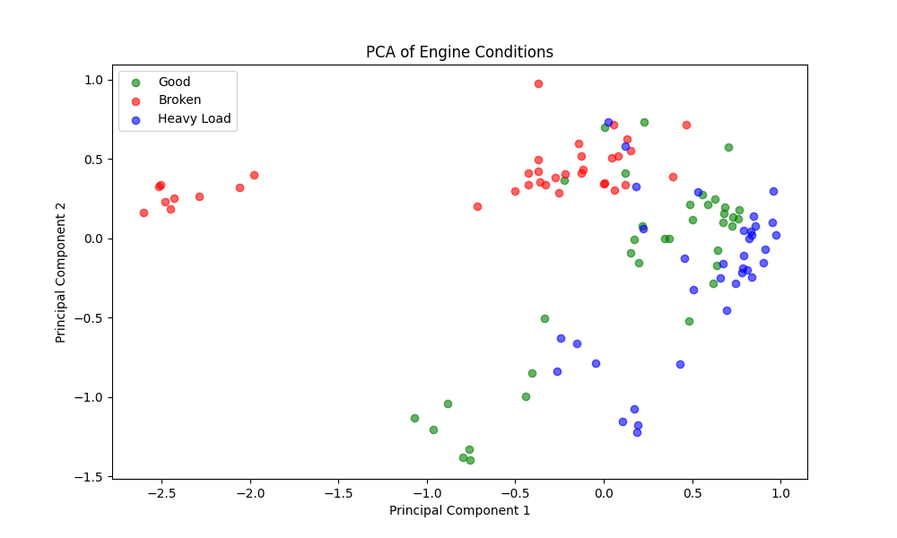
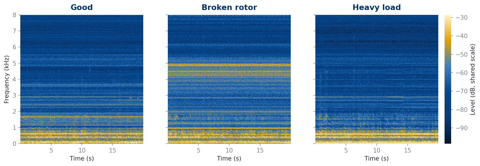
atmo_medium1)
from each class folder, first 20 seconds, shared colour scale. They show what the input data looks like; the
differences may reflect the motor and recording session as well as its condition, so read the confusion
matrices above for performance.
View the original figures generated by the training script
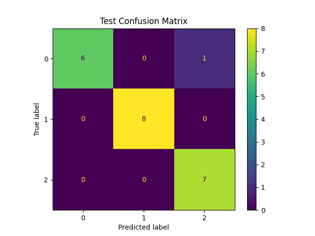
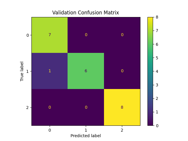
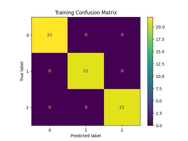
Axis labels 0, 1, 2 correspond to Good, Broken Rotor and Heavy Load.
Current validation
Where things stand
What has been demonstrated, what is being tested now with the Gen 2 hardware, and what is only planned.
Validated
Completed
- Acoustic condition-sensing concept demonstrated on Gen 1
- 108 labeled recordings
- DSP + ML pipeline implemented
- New acquisition PCB designed and manufactured
- Logisial desktop software developed
In progress
Under way now
- Real-motor testing with Gen 2 hardware
- New real-motor dataset
- Noise robustness evaluation
Planned
Not yet started or completed
- Held-out validation on new data
- Hardware-to-software demonstration
- Multi-motor / multi-brand validation
- IP / certification work
Preliminary Gen 2 experiments show behaviour consistent with Gen 1; formal Gen 2 results will be published. Planned items are targets and have not been completed.
How does AcouTec deal with industrial noise?
Industrial sites are acoustically noisy, which makes noise one of the main open technical questions for any acoustic monitoring approach. Robustness under real industrial noise is one of the current validation objectives and is not yet established.
- Industrial environmentReal factory noise: robustness being validated
- Acoustic captureMicrophone array
- Noise profilingEstimate the background spectrum
- Spectral subtractionSubtract it from the signal
- FilteringButterworth band-pass
- Feature extractionWavelet + spectral features
- ClassificationLinear SVM condition class
Every stage after the first exists in the implemented pipeline. How well the whole chain performs under real factory noise is what the current validation measures.
- Noise profiling
- Spectral subtraction
- Butterworth band-pass filtering
- Multi-channel acquisition (four synchronized channels on Gen 2)
- Feature extraction
- Gen 2 hardware on real motors under operating conditions
- Whether the four-channel array improves results compared with a single microphone
- New data collection to re-validate the model
- That AcouTec is immune to industrial noise
- That it works reliably in noisy factories
- That the Gen 1 results represent performance on a factory floor
Pilot
What does a pilot involve?
A pilot is a joint evaluation of the system on your equipment. Scope and duration are agreed case by case.
Industrial partner
- Motor and application information
- Operating context
- Access for measurements
AcouTec
- Sensing unit
- Data acquisition
- Analysis and evaluation
Pilot outcome
- Documented observations
- Validation results
- Scope agreed case by case
Pilot workflow
- 1
Select a motor / application
Together we choose an industrial motor and the application it serves.
- 2
Position the sensing unit
The AcouTec sensing unit is positioned without modifying the motor.
- 3
Collect acoustic data
Sound is recorded under known operating conditions.
- 4
Analyze and compare
The recordings are analyzed and compared.
- 5
Evaluate against known conditions
The system is evaluated against known motor conditions.
- 6
Improve and validate
The results are used to improve and validate the system.
A pilot does not promise guaranteed accuracy, return on investment or fault detection, a fixed deployment time, or a predicted failure date. Its purpose is to evaluate and validate the system on real equipment.
Market
Market context
Third-party market research, shown for context. It is not AcouTec's own research.
Global predictive maintenance market projected for 2033, from an estimated $14.29B in 2025 (27.9% CAGR, 2026–2033)
Source: Grand View Research, Predictive Maintenance Market report (Jan 2026)
Motor monitoring market, 2026 estimate, projected to reach ~$3.64B by 2031 (6.82% CAGR, 2026–2031)
Share of the motor monitoring market held by vibration analysis in 2025, the largest technique segment
Figures are estimates published by the research firms named above. Reports use different definitions and their estimates vary between publishers. They describe whole markets, not AcouTec's addressable market or revenue.
Business model (planned)
A planned hardware-plus-software model
Acquisition unit
Intended to be sold or financed per monitoring point. Commercial terms are not yet defined.
Logisial Essential
Planned: Good / Not-Good classification, threshold alerts and a single-motor dashboard.
Fleet monitoring
Planned: multiclass condition classification, historical trending, a multi-motor dashboard and exportable reports.
CMMS / SCADA integration
Planned: CMMS/SCADA API access, custom alerting, priority support and over-the-air model updates.
Pricing to be defined through pilot discussions and market validation. No prices have been set, and these tiers are a planned structure, not validated commercial offers.
Roadmap
Planning targets, from validation to early pilots
Technical validation
- Finish validating the new PCB
- Record a new multi-brand dataset
- Retrain and document measured performance
- Build the ProtoMarket 02 demo
Field validation
- 2–4 design-partner facilities
- Harden the enclosure and hardware
- Develop the Logisial software further
- Begin IP groundwork
Early pilots and funding
- Explore paid pilots with design partners
- Pursue grants and initial funding
- Explore channel partnerships
- Begin certification planning
Planning targets — subject to technical validation, pilot feedback, and funding. Dates are not guaranteed.
Team
Led by an automation and industrial computing engineer
Hadjou Ayoub
Founder · Automation & Industrial Computing Engineer · Algeria
Hands-on industrial background: fault diagnosis in manufacturing (marble and granite processing) and electronics repair. That experience shaped the problem AcouTec addresses.
Founder and project lead: system architecture, project development, the DSP and machine-learning pipeline, software development, prototype integration and industrial validation.
- PLC programming
- SCADA
- Variable-frequency drives
- Electrical cabinet installation
- Fault diagnosis
Let's Talk
Interested in testing AcouTec on an industrial motor?
AcouTec is a prototype in validation and is looking for design partners, feedback and funding. It is not yet a commercially deployed product.
Design partners
2–4 real facilities to pilot the new hardware and validate results in the field.
Feedback & expertise
Maintenance teams, industrial partners, and IP/regulatory guidance.
Grants & funding
Building on the Label Projet Innovant toward the design-partner phase.